
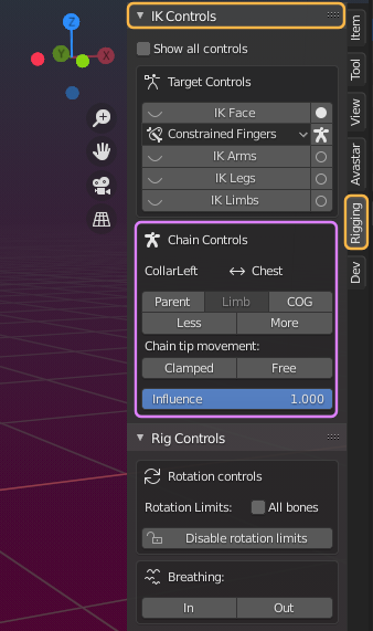
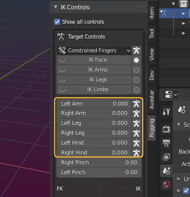
The IK Controls panel (Inverse Kinematics) can be found in the Properties Sidebar of the 3D Viewport – in the vertical Rigging Tab (see image)
Tip: If the sidebar is hidden:
- Make sure the mouse is in the 3D View.
- Hit the ‘N’ key to toggle the sidebar visibility.
- Make sure you have selected the vertical Rigging Tab
- The panel shows up on the right side of the 3D View (in the N-Panel)
The panel displays different sets of properties depending on what bones are currently selected and visible.
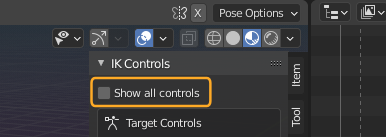
Enforce display of all controls
Unhide IK Bones
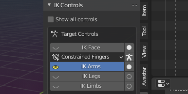
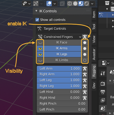
You can unhide (display) the yellow IK Control bones by clicking on the Buttons:
- IK Hands (by default set to FK Constrained)
- IK Arms
- IK Legs
- IK Limbs

Tip: The white running stickman icon is for copy the rotations imposed by the IK bones over to the associated FK Bones, see the chapter IK Bone controls below for an explanation.
You can activate the IK Control Bones by ticking on the hollow circle on the right side of the Buttons (See image) The hollow circle changes to a filled white circle when the IK controls are active. Click again to deactivate the IK Bones again.
Note: For the fingers its different: Clicking The white stickman icon copies the current IK Pose into the FK Bones.
Caveat: You can activate and visualize the IK Bones separately. Remember:
- The filled white circle tells: IK Bones are active.
- The yellow eye icon tells: The IK Bones are visible.
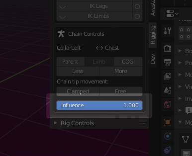
Chain Controls (Targetless IK)
The Chain controls are only available for the (green) control bones.
The Avastar bones are organized in parent/child chains. These chains are used for targetless IK. That is when you grab one bone along a chain, all bones of the chain follow along the movement of the active bone. such as when you move a wrist or an ankle, the entire arm/leg will be moved in a meaningful way.
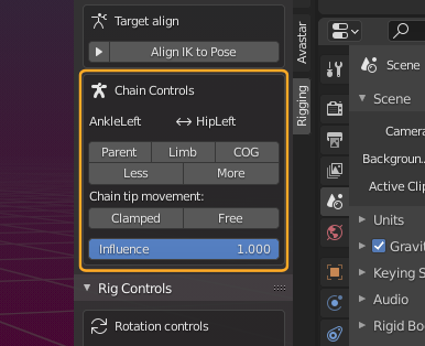
Note: The Chain Control is only shown when the active and selected bone is a green control Bone.
Once you understand how the chain controls work you will find that positioning a character becomes very fast and easy.
The Chain ends
In the top row of the Chain controls subpanel you see the Chain end points for the active (selected)bone. The left entry is the chain start bone, which is always the active Bone. The right entry is the end of the kinematic chain.
Below the Chain display you find 5 control Buttons which allow you to quickly change the end of the Chain:
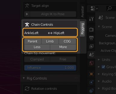
Parent
The chain begins at the current bone and ends at the Bone’s parent. This is the smallest possible IK Chain (has only one bone).
Limb
The chain start at the current bone and ends at the last limb bone. These are:
- The Hips (for the leg chains)
- The Collars (for the arm chains)
COG (Center Of Gravity)
All kinematic chains end at the COG Bone, So the COG Bone will always be the most distant bone that you can choose.
Less & More
With these Buttons you can elongate the Bone chain until the chain end reaches the COG Bone, or you can shrink it until the chain end is the parent of the active and selected bone.
Note: Each bone has its own targetless IK Chain. So it is possible to configure the Wrist bone’s chain to reach up to the COG Bone, while the Collar Bone’s chain already ends at the Torso.
The Chain Tip Movement:
The second set of buttons affects how the selected bone behaves when it is moved in Pose mode. In the example below i have moved the Avastar’s mNeck Bone along the X-Axis to show the difference between Clamped and Free Bone Tip Movement:
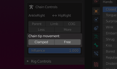
Clamped: the chain tip moves but does not rotate. It will keep it’s orientation in space as it’s dragged around.
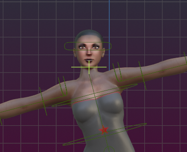
Clamped: Bone orientation does not change while bone is moved
Free: the chain tip moves/(rotated) freely with the movement of the bones

Free: Bone Orientation is controlled by the IK Resolver
Influence
IK Targets
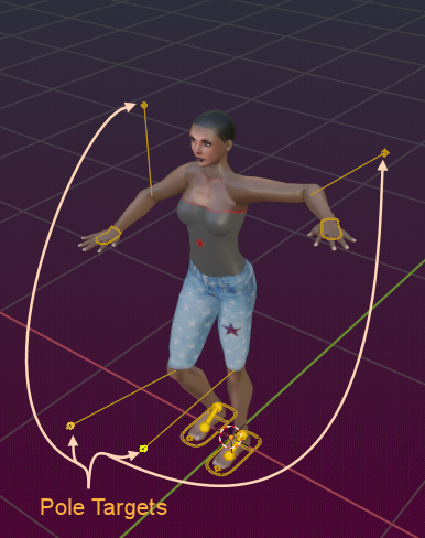
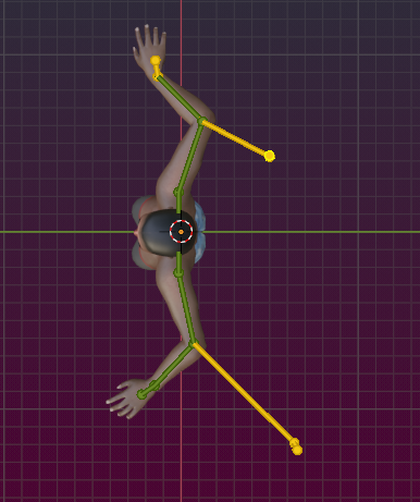
Avastar provides 6 IK Target bones, 2 for the Arms and 2 for the Avatar legs and 2 for the Extra limbs (from the Bento skeleton). These bones are displayed in yellow.

Besides the IK targets we also offer 6 Pole Target bones for adjusting the knees and the elbows (as shown in the image). Besides this we also have 2 Pople Targets for the Hind knees (not shown)
The pole targets are connected to the skeleton via helper bones to visualize where they influence the Skeleton.
IK bone Controls
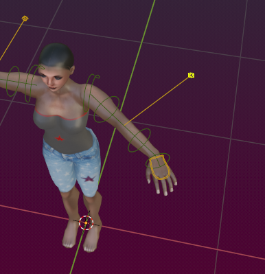
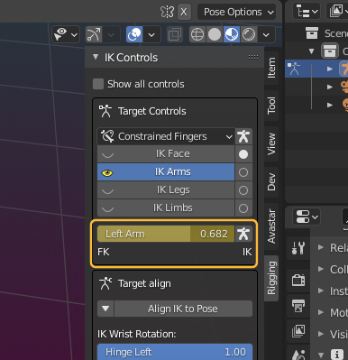
The 6 IK Targets (yellow) are mainly used to clamp the limbs at fixed positions. We have 3 sliders for each limb plus 2 additional sliders for the Foot Pivot. I have enabled Show all controls so we can see the control parameters without actually selecting the bones. Read on for more details…

IK/FK influence:
The 6 sliders (Left/Right Arm, Left/Right Leg, and Left/Right Hind) define the amount of influence that is applied from the IK Control bones to the corresponding limbs.
By default the IK influence is set to 0, that is: the bones are completely decoupled from the IK control bones and thus they behave solely as FK bones (FK==forward kinematics).
If you move the sliders towards a value of 1, then the current location of the IK bone controller gets more influence on where the tip of the corresponding bone chain is located.
Besides the sliders as described above we have added shortcuts for:
- Fully Enable/Disable the IK influence (the hollow/filled white circles)
- Show/Hide the IK Bones (the closed/open eyes).
Think of the yellow IK Bones as magnets which attract the bone chain tips with a force corresponding to the slider value.
When set to 1, then the tip of the limb chain is fully attracted to the IK Control bone.

Fully FK controlled (value=0.0)
Fully IK controlled (value=1.0)
Note: The bone chain tip (last FK bone in a limb) is not necessarily located where the IK Bones is. When the IK Bone is out of reach, then the Skeleton gets oriented towards the IK bone. But the bones do not stretch!
Tip (for animators): most of the IK control values can be key framed.
Hover the mouse over the value, then press “i”. The value will then display with a yellow background.
Copy IK Poses into FK Bones
Sometimes you want to mix the usage of IK constraints with free limb movement during an animation. However when you enable or disable the IK Bones, then the FK Bones might jump to different locations. So it becomes necessary to make sure that the FK Pose matches to the IK Pose at the moment where you switch from FK to IK or vice versa.
For this purpose we have added the running white stickman which is displayed on the right side of the IK influence sliders. Clicking here copies the current Bone rotations of the IK Bone chain over to the corresponding FK Bone chain.
When you now change the FK/IK influence slider, the pose should not change any more.
Note: The same feature also exists for the fingers if they are constrained

When to (not) use IK
It might be confusing just when to use IK bones. Here are some rules of thumb:
- Use the IK Bones when you want the feet, hinds or arms to keep fixed at a location, while the rest of the body moves.
- Use FK Bones when the Chain ends of the limbs are moved during the Animation.
- Note that the FK Bone chain has a built in auto IK. Therefore you always can select the wrists and drag them around when you are in FK mode.
Foot Pivot
Note: Blender allows key-framing of sliders as well as of bones.
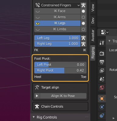
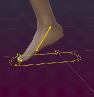
Pivot slider at 0.9 (rotate around the toes)
(
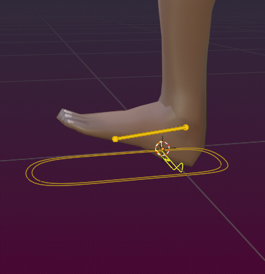
Pivot Slider at 0.0 (rotate around the Heel)
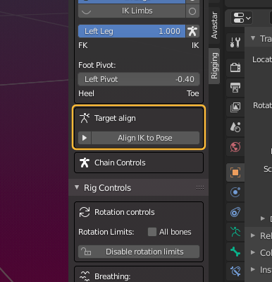
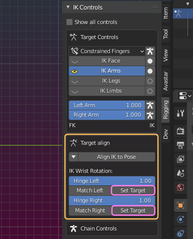
Target Align
The targetless IK is a great way of posing a character. However, when you want to switch to targeted IK in the middle of your animation, then you probably see a mismatch of the IK Control Bones to their corresponding IK Bones.
The Target Align Tool fixes this easily as follows…
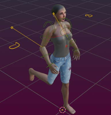
Possible Bone Mismatch when switching to IK Animation
When you have selected one or more bones which belong to a bone chain, then an additional subpanel opens. The Target Align panel allows to set the IK Properties of the rig. By default the properties area is collapsed as shown in the image.
We will describe the content of this area below in more detail.
When you Click on the Button Align IK to Pose then all affected parameters of all currently selected IK Bones are set at once:
- Select the misaligned yellow IK bones
- Click on the Button Align IK to Pose
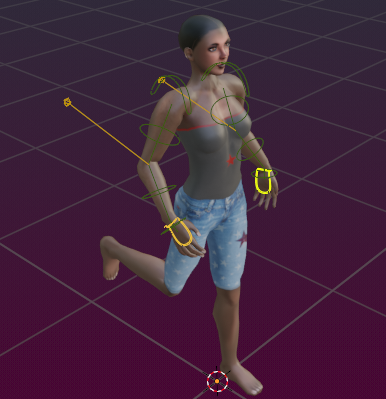
IK Control Bones match after apply align IK to Pose.
Wrist & Ankle Rotation
You also can fix the IK Bone locations individually by using the Target Align subpanel:
In the Target Align Panel you find up to 6 Match Buttons (depending on which of the IK Control Bones you have selected):
- Match Left Wrist.
- Match Right Wrist.
- Match Left Ankle.
- Match Right Ankle.
- Match Left Hind
- Match Right Hind
These Operators copy the current rotation and location of the corresponding wrist bone or ankle bone to it’s corresponding IK Bone.
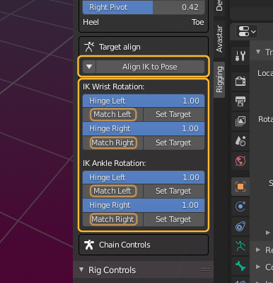
The Target Align Buttons only appear when you have selected an IK Control Bone (yellow)
Set Target
While you work with the IK Bones the target poles often get into weird positions. Either automatically while you move the IK Targets or manually when you move the IK Poles.
You may occasionally want to reposition the poles to a more convenient place without destroying the current pose.
Before Set Target is called the yellow connection line can be at an arbitrary orientation.
These Operators orient the connection line between the pole target and its corresponding bone perpendicular to each other.
the line bones are then arranged such that they cat the angle between the Elbowes and Shoulders into half.
Note: This alignment works reliably only for the arms. For the legs the situation is little bit more complicated and the automatic alignment does not work perfectly because the bone rest poses of the leg bones are not aligned like it is the case for the arms.

After Set Target is called the connection line is oriented perpendicular to the shoulder bone.
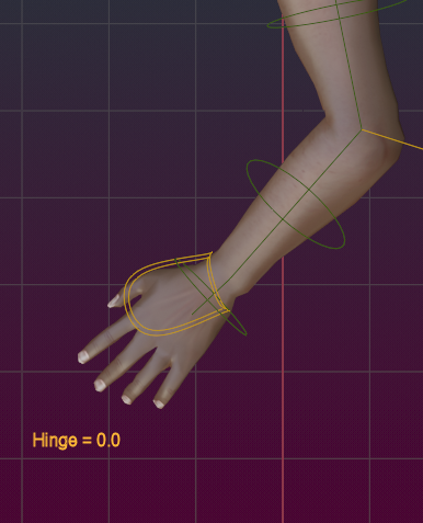
Set Hinge
The hinge sliders define how much the wrist rotation is influenced by the IK bone controllers.
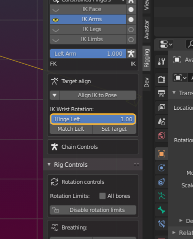
- Slide it to the left (0.0): The IK Control bone has no influence on the wrist rotation.
- Slide it to the right (1.0): The rotation of the IK control bone is fully applied to the wrist.
