Creating the Avatar Workbench and Avastar has given us great insight on the SL avatar. The goal of this article is to give you detailed information about the construction of the Second Life avatar and what you can do with it.
We will also talk about some areas where we simply do not know what happens, or where there are inconsistencies and the techniques are highly experimental. We’ll update the page as we learn more.
This page includes the Bento Bone definitions which will come to the Second Life main grid sometime this year (2016)
In a nutshell…
The Second Life Skeleton supports:
Basic Bones
- 26 Basic bones
- 32 Basic Attachment Points
- 26 Collision Volumes
Extended Bones
- 104 Extended Bones
- 13 Extended Attachment Points
The Skeleton is further controlled by a set of 120 Shape parameters (Accessible via the Appearance Editor in the SL Viewer) to define the character’s general Shape (tall-tiny, fat-slim, muscular-shape, etc…)
Conceptual information
The Base Skeleton
The skeleton uses 26 bones for driving
- the body (split into two meshes upper and lower),
- the head and hair meshes,
- the skirt mesh,
- the eye meshes.
Note: 5 Bones are not used for weighting of the System Avatar. The bone names are displayed in Cyan blue in the Listings below.
The 26 Base Bones
The defined Base Bones are:
- mEyeLeft
- mCollarLeft
- mShoulderLeft
- mElbowLeft
- mWristLeft
- mHipLeft
- mKneeLeft
- mAnkleLeft
- mFootLeft
- mToeLeft
- mSkull
- mHead
- mNeck
- mChest
- mTorso
- mPelvis
- mEyeRight
- mCollarRight
- mShoulderRight
- mElbowRight
- mWristRight
- mHipRight
- mKneeRight
- mAnkleRight
- mFootRight
- mToeRight
So only 21 base bones are effectively used to create animations for the system Avatar, and only these bones are associated with weighting information for the Base Bones of the Avatar. That is, even if you animate the remaining 5 bones, the animation will not contribute any skin movement to the system Avatar.
However, we will see later that you can use all 26 bones for weighting and animating your own custom meshes.
The Extended Skeleton
The Basic Skeleton is only capable to animate very simple movements. Large portions of the mesh are simply left out and can not be animated in detail (at least not directly, see below) Especially non human creatures can not be nicely animated only with the base Skeleton. This gap is filled by the Extended Bones, a set of 104 extra Bones which are organized into 5 Subsets:
Face Bones: (44 regular bones + Face Root)
The face rig is connected to the SL Appearance Sliders. That is the Face bones move along with the Appearance sliders. So if your mesh characters are weighted to the Face bones, then many of the face appearance sliders now also affect your character look.
But note that the shape sliders affect bone location (bone translation). So the face shape may be affected by custom animations as well (see below for details).
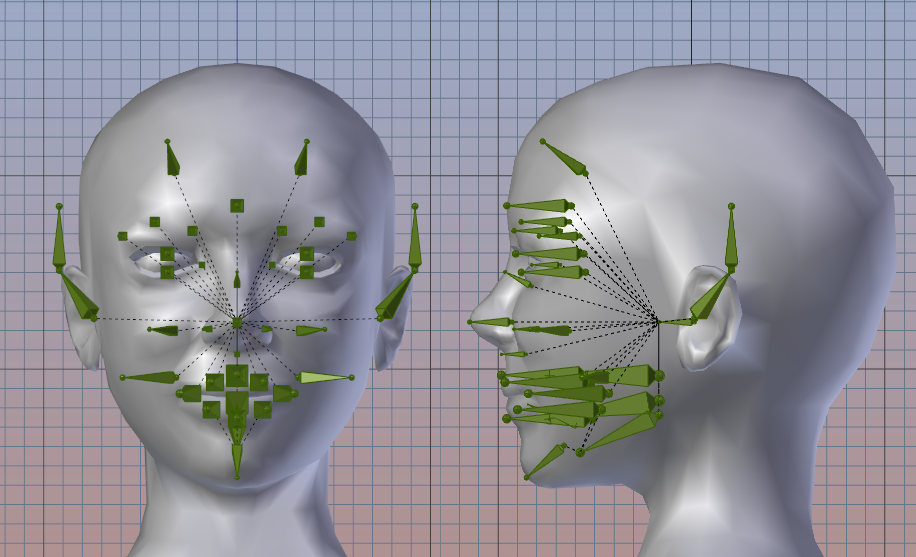
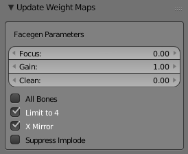
Avastar: Face Weight Generator
We have created a Face Weight generator, a tool that is aimed to help creating weights more easy. However this tool is a bit experimental. It might work well or not for your particular mesh creations.
Calling the Face Map Generator
You find the generator in the Weight Map Control panel within the Toolshelf (You need to open the Avastar vertical Tab first and your mesh must be in weight paint mode)
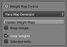
Tweaking the Maps
Once you called the Generator it will operate on the weight maps for the selected bones and when done it opens an Operator Redo panel at the bottom of the Tool shelf. There you can tweak the parameters further to optimize your weight maps.
An animation pitfall
The Face bones are used by the appearance slider system to adjust the facial shape also for mesh heads. But the bones are also moved by the Second Life animation system. This results in a possible dependency between the Face Shape and facial animations (smile, frown, …).
Rotation Animation
As long as an animation only uses bone rotations the animation plays on top of the shape and the facial shape will be more or less preserved while the animation plays.
Translation Animation
The SL animation system also allows to use Translation animation. However this interferes strongly with the appearance slider system.
An animation that modifies bone location while playing will always destroy the face shape while playing.
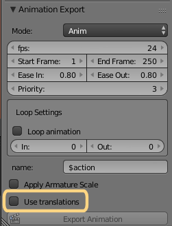
Note for Avastar users
You can enforce to export only rotation channels when you use the Avastar .anim (or .bvh) exporter (see image):
When you disable the Option “Use Translations” then the exporter only exports rotation information. But note, this can potentially end up with unexpected results when you later play the animation on your character.
side note: We may need to add some work into the exporter to map transition changes into bone rotation changes (which can be done if the local root bones are not moved)
Face Bones (46)
- mFaceEyeAltLeft
- mFaceForeheadLeft
- mFaceEyebrowOuterLeft
- mFaceEyebrowCenterLeft
- mFaceEyebrowInnerLeft
- mFaceEyeLidUpperLeft
- mFaceEyeLidLowerLeft
- mFaceEyecornerInnerLeft
- mFaceEar1Left
- mFaceEar2Left
- mFaceNoseLeft
- mFaceCheekLowerLeft
- mFaceCheekUpperLeft
- mFaceLipUpperLeft
- mFaceLipCornerLeft
- mFaceLipLowerLeft
- mFaceRoot
- mFaceForeheadCenter
- mFaceNoseCenter
- mFaceNoseBridge
- mFaceNoseBase
- mFaceLipLowerCenter
- mFaceLipUpperCenter
- mFaceJaw
- mFaceJawShaper
- mFaceChin
- mFaceTeethLower
- mFaceTeethUpper
- mFaceTongueBase
- mFaceTongueTip
- mFaceEyeAltRight
- mFaceForeheadRight
- mFaceEyebrowOuterRight
- mFaceEyebrowCenterRight
- mFaceEyebrowInnerRight
- mFaceEyeLidUpperRight
- mFaceEyeLidLowerRight
- mFaceEyecornerInnerRight
- mFaceEar1Right
- mFaceEar2Right
- mFaceNoseRight
- mFaceCheekLowerRight
- mFaceCheekUpperRight
- mFaceLipUpperRight
- mFaceLipCornerRight
- mFaceLipLowerRight
Hand Bones (15 per Hand)
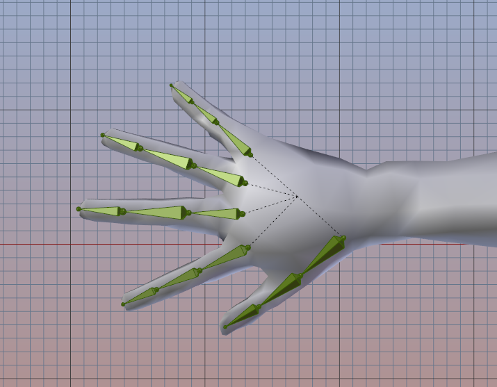
Avastar: Constrained FK and IK Rig
When you use Avastar then you get 2 extra features for easy hand animation creation, that is:
- Constrained FK: Allows you to curl fingers in a natural way by grabbing the finger root bone and rotate it along the bone’s local X axis
- IK: Allows to place IK targets to which the finger tips approach (and keep glued to)
The hand Bones are:
- mHandMiddle1Left
- mHandMiddle2Left
- mHandMiddle3Left
- mHandIndex1Left
- mHandIndex2Left
- mHandIndex3Left
- mHandRing1Left
- mHandRing2Left
- mHandRing3Left
- mHandPinky1Left
- mHandPinky2Left
- mHandPinky3Left
- mHandThumb1Left
- mHandThumb2Left
- mHandThumb3Left
- mHandMiddle1Right
- mHandMiddle2Right
- mHandMiddle3Right
- mHandIndex1Right
- mHandIndex2Right
- mHandIndex3Right
- mHandRing1Right
- mHandRing2Right
- mHandRing3Right
- mHandPinky1Right
- mHandPinky2Right
- mHandPinky3Right
- mHandThumb1Right
- mHandThumb2Right
- mHandThumb3Right
Tail Bones (6)
Not much to say here.
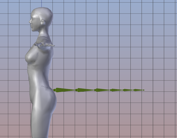
Avastar: IK Rig
When you use Avastar then you also get an IK Meta rig for the tail: Just grab and move the tip around and the other bones follow nicely.
The tail Bones are:
- mTail1
- mTail2
- mTail3
- mTail4
- mTail5
- mTail6
Hind Bones (2*4 plus Hind Root Bone)
- mHindLimb1Left
- mHindLimb2Left
- mHindLimb3Left
- mHindLimb4Left
- mHindLimbsRoot
- mHindLimb1Right
- mHindLimb2Right
- mHindLimb3Right
- mHindLimb4Right
Wing Bones (2*5 plus Wing Root Bone)
Avastar: IK Rig
When you use Avastar then you an IK Meta rig for the Wings: Just grab and move the tips around and the other bones follow nicely.
The Wing Bones are:
- mWing1Left
- mWing2Left
- mWing3Left
- mWing4Left
- mWing4FanLeft
- mWingsRoot
- mWing1Right
- mWing2Right
- mWing3Right
- mWing4Right
- mWing4FanRight
Spine & Groin (4+1)
The Extra Spine and Groin bones are:
- mGroin
- mSpine1
- mspine2
- mSpine3
- mSpine4
120 Appearance parameters
The character can be shaped to a large extent by using the SL appearance editor. The shape parameters can be changed by use of shape sliders.
Within the appearance editor you find 3 sections with 23 shape parameters for the body, torso, and legs. Another 6 sections with 55 shape parameters for eyes, ears, and mouth, as well as for the nose, chin, and the head form. In addition there are 42 controls for the clothes morphs.
| Body | 3 | Shirt | 7 |
| Torso | 12 | Pants | 6 |
| Legs | 8 | Socks | 1 |
| Shoes | 7 | ||
| Head | 11 | Jacket | 6 |
| Eyes | 11 | Skirt | 7 |
| Ears | 4 | Gloves | 2 |
| Nose | 11 | Undershirt | 4 |
| Mouth | 9 | Underpants | 2 |
| Chin | 9 |
When you just work with the default avatar, then you can create small and fat avatars as well as large and slim characters only by adjusting the shape parameters according to your taste. You can do all of that in your Viewer without need to use an external 3D tool.
However, when you use Custom Meshes then some different rules apply…

Mesh and Appearance Sliders
If your 3D world supports mesh items (like Second Life, OpenSim, RealExtend, inWorldz and others…), you also can create your own character meshes. You can create mesh based attachments for either the standard character or for your own mesh based characters.
In fact only the bone changing shape parameters influence the mesh based attachments and characters. That is, mesh attachments can not be fully customized by using the Shape sliders. This restriction can be a major problem with mesh attachments.
Shape and Skeleton matching
It is important to always remind that your Avatar Shape settings in your viewer effectively change your skeleton’s joint positions and Bone Scales. This is controlled via 20 of the available shape parameters (appearance sliders) for the Legacy Skeleton and 40 additional parameters for the Extended Skeleton (mostly for the Face expressions and Hands).
So if you want to create a specific mesh attachment for a specific shape then you need to know exactly how the shape values are related to the joint positions (and bone scales) of your particular shape. But this information is normally not available outside of Second Life.
Fortunately you can get around this problem by using the SL Restpose for your work in your 3D Editor. However this means you create your content by using the Second Life Restpose which does never match the actual Shape that you use in Second Life.
Actually we want to create attachments which can be adjusted (fitted) to any shape. This is where the Fitted Mesh addition steps in. The basic idea is to let more Appearance sliders control the mesh. This is done by using the Fitted Mesh bones, or more precisely the Collision Volume Bones to the mesh.
Shape parameters influencing the Base skeleton
The list of bone length changing Shape keys. Please note, the shape keys marked in orange do also influence the Collision Volumes (see next chapter)
|
Collision Volumes (Fitted Mesh)
The default avatar uses 24 additional so called Collision Volumes. These are simplified mesh volumes for calculating when an object or another avatar is bumping into a character. In fact the Collision Volumes are a set of 24 Octahedrons which get influenced by various shape sliders.
Interestingly these volumes are also counted as full bones, and they can be animated and weighted just like the standard bones. The most interesting property of these bones is that they get moved and scaled by some of the shape keys. Weighting mesh clothes or avatars to these bones means they will respond to the Shape keys, for example Torso muscles.
But note that only a very small fraction of the Shape sliders actually does influence the Collision Volumes. thus you can not expect to get a full control over your mesh object by using the Collision volumes. for example changing the breast shape is not at all mapped to collision volumes. As well as facial expressions are not supported.

Shape keys and the Collision Volumes
This is the list of Shape keys which do affect the Collision Volumes. Please note, the shape keys marked in orange do also influence the Bone length (see previous chapter)
| Body | Height, Body Thickness, Body fat |
| Head | Head Size, Head Stretch, Head Length |
| Torso | Torso Muscles, Neck Thickness, Neck Length, Shoulders, Arm Length, Hand Size, Torso Length, Love handles, Belly Size |
| Legs | Leg Muscles, Leg Length, Hip width, Hip Length, Butt Size, Saddle Bags, Knee Angle, Foot Size |
We already know that we can modify the Second Life default Skeleton by using the Appearance Sliders. But this is not all we can do. In fact it is possible to rearrange the Skeleton in any way we want. There are only 3 basic rules:
- We can only use the existing set of Joints (bones).
We can not add new joints to the Skeleton. - We must keep the hierarchical Joint structure as it is.
We can not rearrange the joint hierarchy of the Skeleton. - We are free to move the existing Joints wherever we want.
In first place this might sound like a strong limitation. But you quickly see that you can create a wide variety of creatures only by rearranging the existing bones. However there are a few things you need to know before you jump into the deep waters…
Joint Offsets
As mentioned before we only can rearrange the location of Joints but not their relationship. Because of this we always can define a modified skeleton just by recording how far each Joint has been moved away from its original location. This distance is the Joint Offset
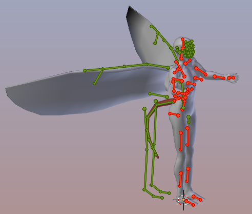
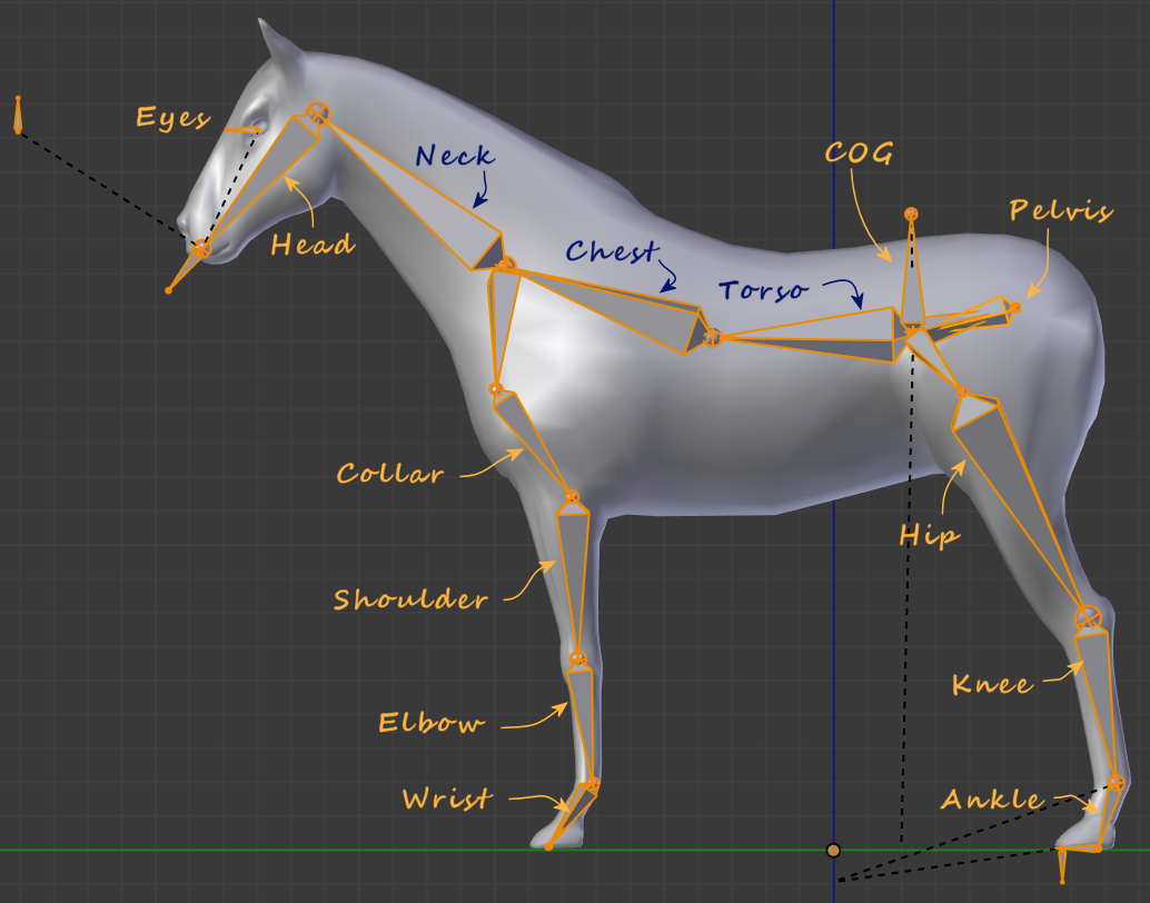
So one way to define the modifications of the Skeleton is by recording the Joint offsets for all Joints (the small dots in the image on the right side).
The image shows the default SL Skeleton in its T-Restpose (the orange skeleton). And a modified Horse Skeleton (the grey Skeleton). The blue lines mark the offsets from original joints to the modified joints.
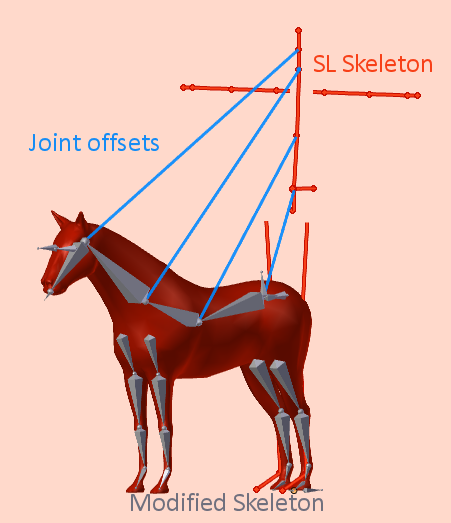
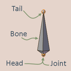
Blender uses Bones with a Head and a Tail. the Head is very similar to what other programs name Joint. The Tail is not supported by other programs. The dots at the end of a bone chain are always bone tails, so those final dots are not Joints!
Defining Joint Offsets
The good news is: You only need to move the joints of your Skeleton into place. For Blender users: You can do this by selecting your Skeleton (the Armature) in EDIT mode and then move the bones one by one.
So, how does Second Life know if a Skeleton uses joint offsets? The Second Life importer decides this for each joint by checking if its location is close to the default joint location of the SL Skeleton in Rest pose. As soon as a joint is offset by more than 0.1 millimeter it is counted as a joint with offset.
Note: The joint offsets are only checked when you enable “with joint positions” in the SL Importer’s Option tab.
Create your modified Skeleton by moving the joints one by one into place.
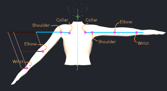
Checking your joints in the Viewer
The SL Viewer allows you to display the Skeleton Bones. You enable the bone display in the Develop menu under:
Develop -> Avatar -> Show Bones
- Joints are displayed as small dots (pink in the image for better visibility)
- Weighted Joints without Joint offset are displayed in Cyan
- Weighted Joints With Joint offset are displayed in Red
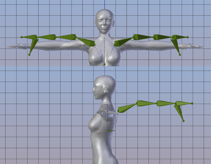
The SL Viewer shows the Joints at their expected locations. But the bone orientation (the colored lines) are always taken from the Restpose Skeleton.
The model shown in the image above has only its right arm edited into an A Rest Pose. You can see the joint locations are displayed where we expect them to be. But the Bone orientation (the lines) are not rotated as you might expect.
If you take a closer look into this then you find the Bones orientation is always taken from the Restpose orientation. Because of this the bones of the right arm do not line up as expected but point to the right (left from your point of view).
here you see how the “bones” are just translated (moved) from their original locations to the offsets.
A surprising behavior
The Appearance slider behavior depends on whether a joint has offsets defined or not:
- For regular joints (without offsets) the appearance sliders can influence the joint location (Translation) and the Scale
- As soon as a joint has an offset, the Translation part is disabled
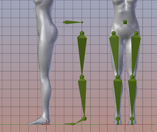
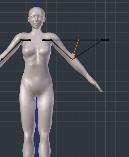
But you also must know that the orientation of the Joint scaling does not change. This is important as you can see in the image aside. In this example the right arm has been edited to point straight downwards. While the left arm remains unchanged.
This results in drastic differences how sliders influence the arm length.
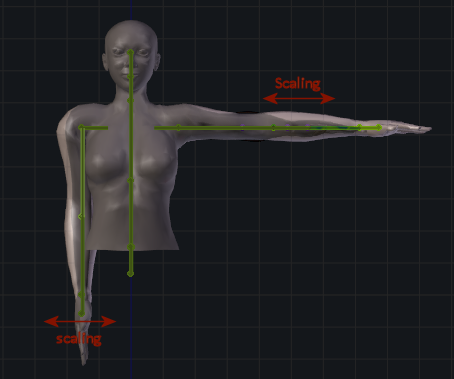
The scaling orientation does not change for joints with objects. This can result in very unexpected behavior. Here you see how the arm length slider changes the length of the right arm and the thickness of the left arm.
You can verify the arm length slider changes the length of the left arm (as before) but the thickness of the right arm (very unexpected, but works as designed).
And a nasty Pitfall
Now lets turn back to the horse from our initial example (see above). Lets say the mChest Bone of this horse has not been used for weighting the mesh (just as an example). The mChest bone lies in the middle of the Bone chain that starts at the mPelvis and ends at the mHead
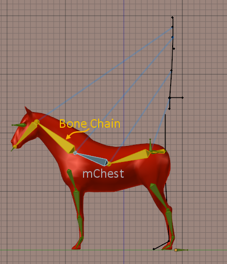
Since Bento it is possible to only import partial skeletons. Especially you can decide to only export the weighted bones of your character (because unweighted bones are not used for deforming your mesh). So, when you import this horse with the Bento Viewer, then the mChest bone is not imported. But…
During importing your character all “missing” bones are taken from the original skeleton. But the SL Importer has no way to find out where the mChest bone has been placed in the original model. So it simply keeps the mChest bone at its default location . And this results in a skeleton where no joint position is defined for the mChest.
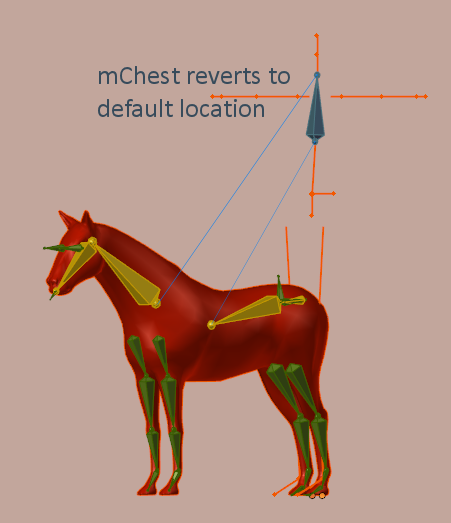
So even if the mChest bone plays no role in the character weighting (in our example) it still affects all its children as far as appearance sliders are concerned, because it reacts different to the appearance sliders when it has no joint offset defined.
Now you wonder why this is important even if you do not at all use the appearance sliders? In fact the appearance sliders take effect even when you wear a default shape. But this is another story.
What about PIVOT and POS
You may have seen that Avastar supports 2 Joint Types, namely PIVOT and POS. But what is that and how do we work with this? In fact this is one other source of misunderstanding, misbehavior and its quiet badly understood by everybody, even by LindenLab them self (i believe).
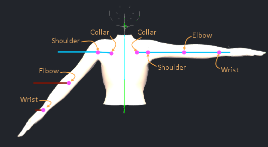
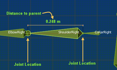
In short POS and PIVOT are 2 definitions of the Secondlife Rig which are almost identical but differ a tiny bit from each other. The reason for why those 2 rig definitions exist is unclear and buried somewhere in ancient history of Secondlife. Below you find an excerpt of the Rig definitions. The values are 3 dimensional vectors. Each vector defines the distance to the parent joint:
Bone
mCollarRight
mShoulderRight
mElbowRight
mWristRig
 Pivot-Rig location offsets
-0.020927 -0.085000  0.165396
 0.000000 -0.079418 -0.000000
 0.000000 -0.248000 -0.000000
-0.000000 -0.205000 -0.00000
 Pos-Rig location offsets
-0.021 -0.085 0.165
 0.000 -0.079 -0.000
 0.000 -0.248 -0.000
 0.000 -0.205 -0.00
For example the mElbowRight joint is exactly 0.248 m (24.8 cm ) away from the mShoulderRight joint in both Rigs (see image)
But the joints mCollarRight and mShoulderRight are placed at slightly different locations in both rigs (see the numbers in the table)
I have marked the differing numbers in orange boldface.
So what?
First of all the 2 Rigs are actually used for different purposes:
POS Rigs
Are only used by the Secondlife System character. The POS Rig is declared as the one Rig that has no Joint Offsets.
So when you import a mesh that was rigged to a clean POS Skeleton then even if you Import with Joint Positions the SL Import willl correctly see that there are no Joint offsets at all defined in the rig.
PIVOT Rigs
Are only used by the Custom Mesh attachments and Custom Mesh characters.
So when you import a mesh that was rigged to a clean PIVOT Skeleton then the SL Importer detects falsely that some bones have Joint offsets.
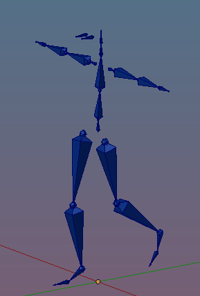
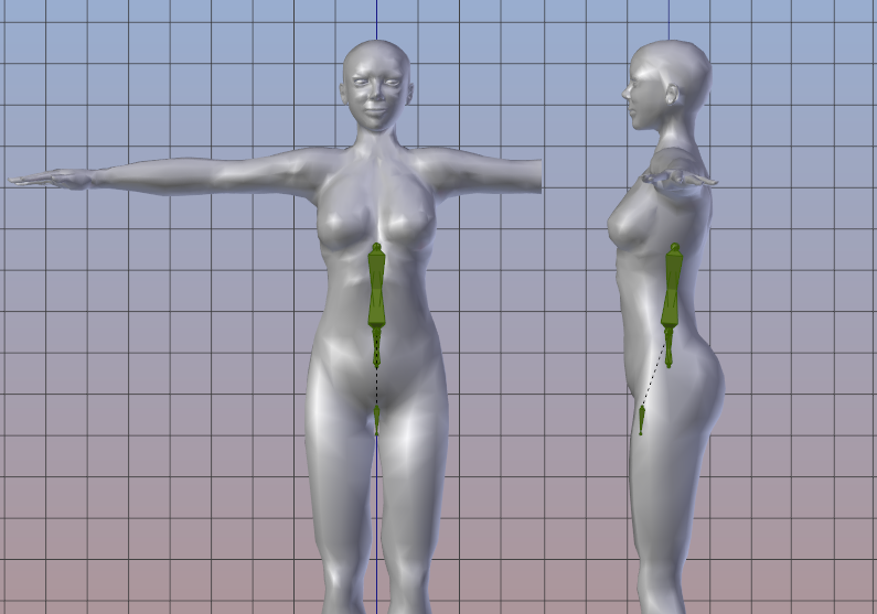
The following 2 rigs both have been created with default Rig values and imported with Joint Positions. Bones with Joint Offsets are marked in Red. You see the POS Rig imports cleanly but the PIVOT Rig exposes Joint offsets although its a perfect clean PIVOT Rig:
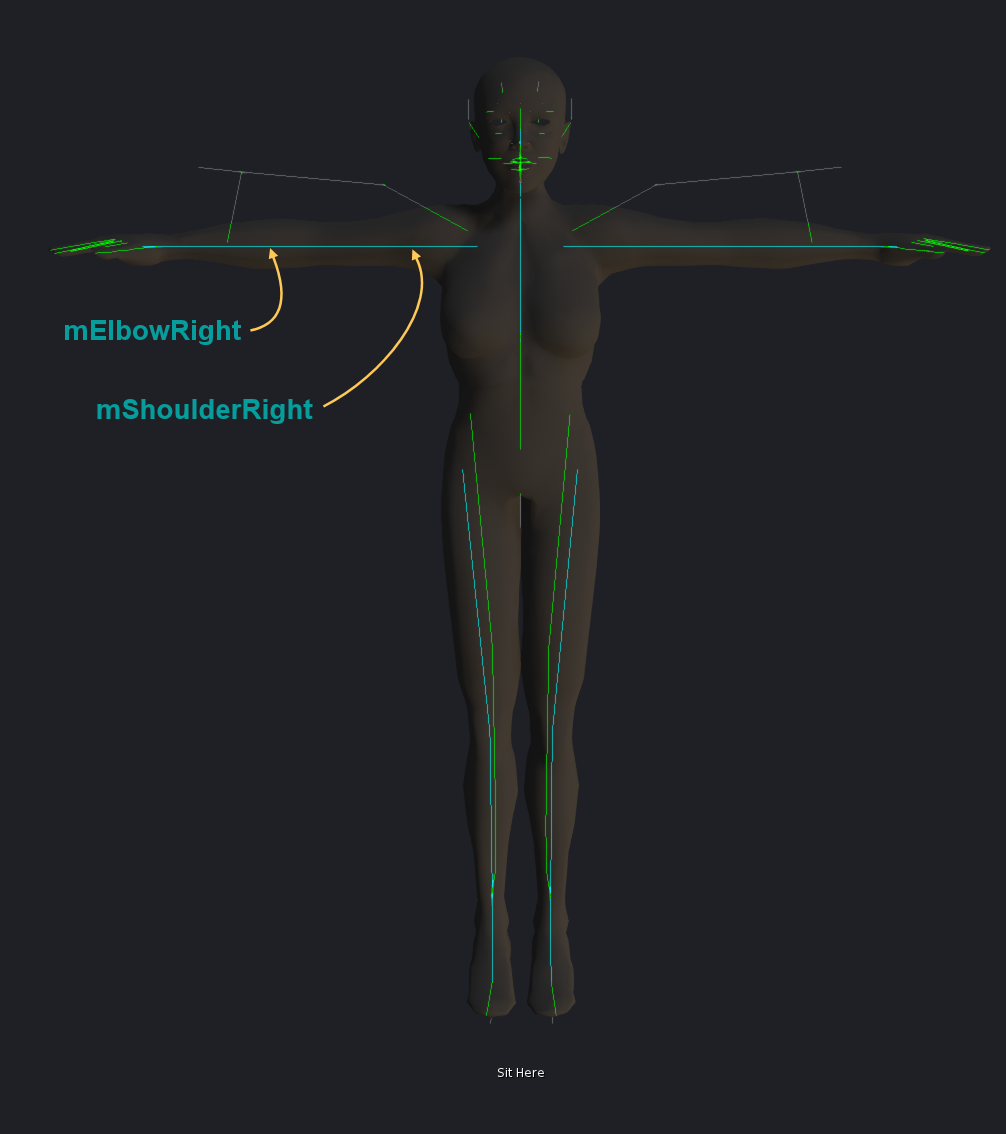
A POS Rig imported with Joint Positions
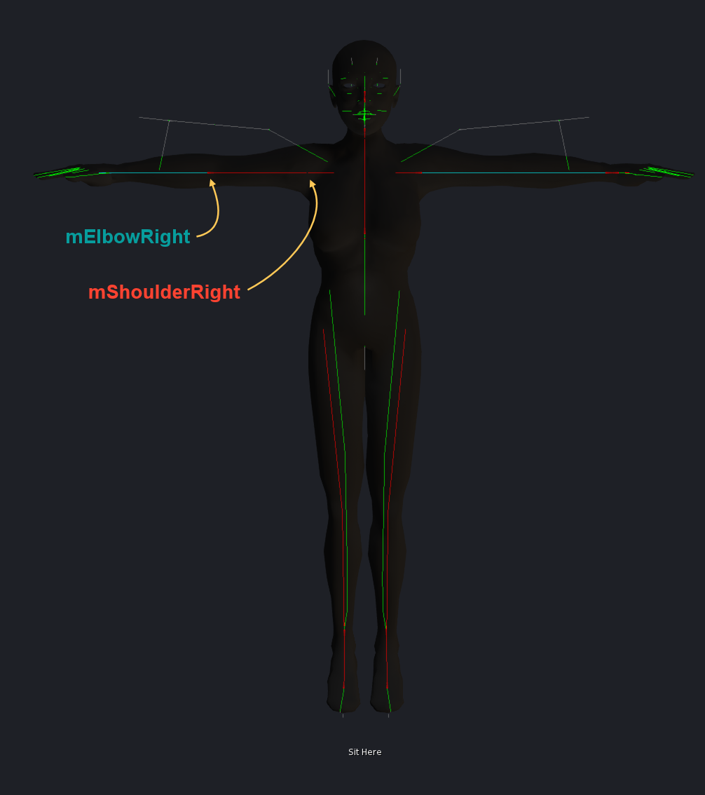
A PIVOT Rig imported with Joint Positions
And here is the Double Salto Mortale
Remember what i said about when is which rigtype used? Here is it again:
- POS Rigs are only used for the System Character
- PIVOT Rigs are only used for the custom Mesh Characters
So as a consequence here is the first Salto:
When you use a clean POS Rig for your mesh character then an import with Joint offsets works just fine and correctly detects there are no joint offsets in the rig. But the Mesh gets bound to a PIVOT Rig and so you will see mismatches when you compare to the System Character.
When you use a clean PIVOT Rig for your mesh character then an import with Joint offsets uncorrectly detects joint offsets for some bones. But the Mesh gets bound to a PIVOT Rig and so it will match better when you compare it to the System Character. But there are still mismatches… why?
And here is the second Salto:
When a Bone has a Joint Offset then it gets treated slightly different by the Appearance system. Technically it loses the ability to follow translations.
That means for the Collar bones and Shoulder bones: When you move the Torso Shoulders Slider then it just does not work any more. And this has major consequences and you end up with a shape that no longer matches to the System character mesh, even when the mesh itself does match perfectly on vertex level.
Summary
Second Life uses 2 slightly different Rig definitions for the System character and for your Custom meshes. Also Bones with Joint Offsets behave different from Bones without Joint Offsets. So …
- Forget to make Mesh characters by using the POS Rig. Otherwise you lose precision in the meshes.
- Forget to import clean PIVOT Rigs with joint offsets. Otherwise you loose precision in the meshes.
- The only reliable way to get good results: Use clean PIVOT Rigs and avoid using Joint offsets when you try to match items to the system character
Attachment Points
 Limitations ahead!
By experimenting with these bones we found some undesirable side effects, which may be due to the fact that weighting and animating these bones has never been seen as a valid option.

The main limitations we’ve discovered are:
- Some attachment points have spaces in their name. Collada 1.4 doesn’t support bone names like this consequently a bone like “Left Shoulder” is interpreted by the Collada Importer as 2 bones with the names “Left” and “Shoulder” respectively, thus the Collada data will be invalid.
- There is no rotation reset. Unlike the normal bones, stopping an attachment bone animation will leave the bone in the last rotated position. To fix you need to run an animation which rotates the bone to zero again.
- Again unlike normal bones it doesn’t appear possible to change the location of the bone with a custom mesh import (Adding joint offsets to attachment bones). Either it gets ignored or the entire armature gets distorted.
![]() We believe that your viewer should be able to use the attachment points exactly like all the other bones, and thus give us 32 extra possibilities for weighting and animating our meshes, and that the existing limitations should be viewed as bugs. But currently it is not possible to weight attachment points in a reasonable (safe) way.
We believe that your viewer should be able to use the attachment points exactly like all the other bones, and thus give us 32 extra possibilities for weighting and animating our meshes, and that the existing limitations should be viewed as bugs. But currently it is not possible to weight attachment points in a reasonable (safe) way.
What we have so far
So we have effectively 77 bones available for animation and rigging. Furthermore 20 Shape keys do influence bone lengths, and 23 shape keys do influence the Collision Volumes. All together (when combining the bone shape keys and collision volume shape keys) we find that 30 Shape keys do influence the mesh and its skeleton provided it is correctly rigged and weighted.So far this is what we found by inspection and experimentation and this reflects our current knowledge about the Skeleton. In the following chapter we will take a closer look on practical issues.
Summary
The Skeleton and the associated Shape key system provide:
- 26 standard bones
- 32 attachment points
- 24 collision volumes
- 120 Shape keys
30 of the shape keys influence the Mesh and/or the Skeleton and thus they can be used for limited customization of custom meshes.
Practical observations
Rigging and Weighting
Lets take a look at an example.
This is a low poly mesh made for game engines. When we want to prepare this mesh for our 3D world, then we have to do following preparations:
- First we need to setup the skeleton itself.
Here we have to take care about the bone hierarchy and about the exact bone names. Otherwise the skeleton is rejected by the mesh importer within your viewer. We believe that you can find an appropriate rig for each of the major 3D editors. - Now we need to find the best fitting Shape for the character.
- Then we have to add animation data, that is, we have to weight the mesh against the 21 standard bones.
- Finally we have to get our creation into our online world. This is done by exporting the mesh from your 3D editor to a Collada file. We provide Collada 1.4.1 here (This is compatible to 3D worlds which use the skeleton described in this document). The used file extension is “.dae”.
There are some caveats in this process, which might lead to more or less serious issues with your mesh. You have to take care about:
- Your mesh must always be weighted to all 21 Skeleton bones. That is, you have to provide weight information for each bone, regardless whether it is used in your mesh or not. And that means, you have to provide all appropriate weight groups, although they may be empty. If only one of the weight groups is missing, then the mesh will be rejected.
- Your entire mesh must be weighted. If only one vertex is not contained in any of the supplied weight groups, then the mesh will be rejected.
- In most 3D editors you must ensure that your character looks towards the positive X axes when it gets exported. Otherwise you may end up with massive distortions when you wear the character
- If you import a mesh with all vertices weighted to zero, then this mesh disappears as soon as you wear it in the online world. However you can rezz it with no problems.
On a special side note: Although the mesh Importer supports the import of textures along with the mesh, this functionality is currently broken for rigged meshes.
Wearing a rigged mesh
Once you have successfully uploaded your mesh to your 3D world, you can wear it just like any other object by attaching it to an attachment point. However rigged meshes are somewhat special, as you can wear them at any attachment point you like. If the mesh is properly created (weighted) then it will self adjust to the skeleton.
Cancel out the Skeleton Shapes
Here is what you would need to do in principle if you want to create mesh attachments which fit exactly to your in world Shape (attention, this is mind boggling):
- You have to know which shape configuration you use in world. Especially you need to know the values of the 20 Shape parameters which affect the Skeleton.
- You calculate the skeleton configuration which results when applying the shape parameters and setup your skeleton accordingly. This is your working skeleton.
- You setup the working skeleton in your 3D editor and use it to create your mesh attachment.
- When you are done, you have to calculate the difference from your actual mesh attachment to how it would have looked alike if you had created it for the default skeleton configuration. And you have to apply that difference to the mesh. This defacto rebases your work from the working skeleton to the default skeleton. The reason why you have to do that, is that the skeleton shape parameters are already “applied” to your working skeleton. So if you would now simply upload your mesh as it is, then these parameters keep applied and when you wear the mesh, your in world shape will apply the parameters again. And that means your 20 Skeleton shape parameters would be applied twice. Please also note that the default skeleton differs for male shape and female shapes.
- Now you export the rebased attachment to your 3D world.
- Now you can wear the mesh. And if you also wear the correct shape (which you used in step one above) then the shape parameters get applied to the mesh and it now fits 100% and looks exactly like you created it in your 3D editor.
We are proud to tell you that our Avastar product does all of that for you automatically in the background. So you do not need to bother with this at all. But it may be good to know about that issue when you intend to create your own mesh exporter tool.